
The ignition system
The internal combustion engine is, as the name implies, a device where a mixture of air and fuel are burnt under certain conditions resulting in the fuel’s chemical energy being translated into mechanical energy. The ‘internal’ portion of the name is derived from the fact that it takes place within the confines of the cylinder of the engine, and the ‘combustion’ i.e. the burning of the air/fuel mixture (A/F mixture) is the process that takes place. So, let’s look at the process in a bit more detail.
Ignition timing
In a two stroke kart engine, the A/F mixture that was squirted into the cylinder via the transfer ports is compressed by the rising piston within the cylinder, because all the other ports (intake and exhaust) have been closed off by the piston. Then, at some exact point in time, the high voltage generated by the ignition system is fed to the tip of the electrode of the spark plug. This high voltage needs to dissipate itself somewhere and it bridges the air gap between the end of the central electrode and the side electrode (or ground) of the spark plug, thus generating a spark. This spark in turn sets the combustion process in motion.
It’s of importance to note that the distance between the central electrode and ground electrode (the plug gap) plays a crucial role in the generation of the spark. An appropriate gap must be provided on the plug to produce sufficient spark to ignite the A/F mixture. If the gap is too small, the spark will likely be too weak and cause the engine to run poorly or with a lower efficiency. On the other hand, if the spark plug gap is too large the spark is unlikely to consistently ‘jump’ across the long distance between electrodes, thus leading to an erratically running engine, or one that doesn't run at all.
The rising piston compresses the A/F mixture, the spark ignites it, and this results in progressive combustion of the mixture as the flame front propagates. The expansion of the combustion gases causes a large pressure rise within the confines of the cylinder and one would want the maximum pressure to reach an optimum value at some point when the piston has passed top dead centre (TDC) to extract the maximum downward force during the power stroke. Because the combustion process doesn’t happen instantaneously and requires a finite amount of time, the spark must take place with a certain amount of ‘advance’ measured in degrees of crank angle before top dead centre (BTDC) shown in the diagram below.

For the sake of illustration, let’s say that the amount of time in milliseconds to achieve maximum downward force at the same point ATDC in the combustion cycle remains constant over the range of engine speeds. That’s not strictly true as it depends on a number of other factors such as turbulence within the cylinder, amount of load on the engine, A/F ratio, etc.
The faster the engine turns, the more distance the crank travels in terms of angle in a given amount of time. So, to achieve maximum pressure at the same point ATDC what this boils down to, is that the angle of ignition advance needs to increase as the rpm of the engine increases i.e. more advance is required (refer diagram on RHS). The same thing applies to a four stroke engine, and for those old enough to recall, it was achieved via the vacuum advance, or centrifugal advance inside the distributor, but is done electronically these days via the engine control unit (ECU) that relies on a number of sensors for its input values.

Static advance
The point at which a voltage spike is sent to the spark plug when the engine is stationary, is known as the static advance. On a two stroke kart engine this is usually measured in millimetres that the piston is below TDC rather than in degrees of crankshaft angle. There is however a direct relationship between these two variables and hence either of them may be calculated using the appropriate formula below. For those not familiar with the math, ‘cosθ’ is the cosine of angle θ, ‘sinθ’ is the sine of angle θ, and ‘acos’ is the inverse cosine, or cosine-1 of an angle.

So, as we’ve seen from the foregoing one needs to advance the ignition timing from the static setting as the revs increase if you wish to get optimum performance out of the engine. One would expect this to be incorporated by the manufacturers of all kart engines but unfortunately this isn’t always the case as we will see later.
Measuring or setting the static advance
Before proceeding further, you need to know what tools are required to either measure or alter the static advance on your engine. The most common method for a two stroke requires the use of a dial test indicator (DTI) that is fitted into the spark plug hole using an adaptor piece as shown in the diagram on the RHS.
In the majority of cases, the ignition’s static advance is measured when a mark on a rotor fitted to one end of the crankshaft is rotated to line up with a corresponding mark on the stator. Should alterations be required, then generally one loosens off the bolts holding the stator to the engine casing and rotates it until the two sets of marks line up.

So to start the process, you rotate the engine to bring the piston to TDC, and this is evidenced by watching the DTI reading. TDC is when the needle of the DTI changes from clockwise to anti-clockwise or vice-versa. Then, zero the DTI. Now, knowing how many millimetres of advance you want set, slowly rotate the engine in the opposite direction to its normal direction of rotation until this value shows on the DTI. Finally, without moving the crankshaft at all, align the marks on the rotor attached to the crank with the corresponding mark on the stator (refer typical diagram on RHS) and lock the stator into position. Because of parallax errors that can creep in, it’s always a good idea to double check what you’ve done by re-measuring the advance that’s just been set to verify that the marks still line up with one another.
Types of ignition systems
For those that can recall ignition systems using a contact breaker (a.k.a. points), those days are long gone and the systems currently used on kart engines are all electronic. They fall into two distinct categories viz. analogue and digital. The analogue ignitions essentially perform the same function as a simple contact breaker, and the timing over the whole rev range remains constant. With the digital ignition systems, these send a voltage spike to the spark plug at a point in time that is dependent on the engine rpm i.e. the amount of advance varies over the rev range.
Let’s now look at a few of the karting engines that we use in South Africa to better understand the finer details of the setting procedure and also what the advance measurements in millimetres translate to in degrees of crank angle over the rev range.
Comer C50 and C52
The ignition system on this engine makes use of a set of spinning magnets (part of the flywheel) rotating past a coil to generate a high voltage spike for the spark plug. This is a simple analogue system and the static timing setting is the timing advance over the whole rev range.
The amount of advance is measured when the leading edge of the trailing magnet (the second of the two) lines up with the left hand side of the long lamination leg of the coil pack as reference. Adjustment of the advance is made by moving the coil via the slotted holes provided.
Regarding the amount of advance for the C50, the current regulations state that a maximum of 3,8mm is allowed but since you may wish to use less than this, the following will provide a guide as to mm advance = degrees BTDC. Note that the values below are only applicable to the C50 engine.
3,0mm 29,0deg
3,2mm 30,0deg
3,4mm 31,0deg
3,6mm 31,8deg
3,8mm 32,7deg
The current C52 regulations allow a maximum of 4.2mm of advance. The following provides and indication of how this translates to degrees of advance on a C52 Engine.
3,4mm 29,9deg
3,6mm 30,8deg
3,8mm 31,7deg
4,0mm 32,6deg
4,2mm 33,4deg
Kid Rok and Mini Rok
These two engines are essentially identical with the exception being that the amount of advance allowed on the Kid Rok was fixed at 3,0mm but has subsequently been changed to ‘free’ (i.e. same as the Mini Rok) under the latest regulations. The ignition type is an analogue one, so the static timing setting is the one that sets it across the rev range.

Once again, one lines up the marks on the stator and rotor (refer diagram above) to set the timing. For information, the correlations between mm and degrees BTDC for this engine are given below.
2,6mm 25,6deg
2,8mm 26,6deg
3,0mm 27,6deg
3,2mm 28,5deg
3,4mm 28,5deg
OK Junior
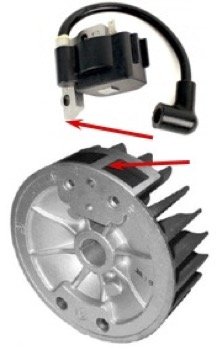
This engine makes use of the homologated PVL Model 684 digital ignition system shown in the diagram. It differs from all those previously discussed in that the amount of advance at start up (static advance) more than doubles by the time the engine speed climbs to 2,750rpm, and then remains constant up until 13,500rpm. It then falls off dramatically should the engine head towards the 14,000rpm mark as shown in the graph below.

Some of the compelling reasons behind the use of this particular digital ignition are to make it a lot easier to push start the kart whilst it only has a little spark advance, and also to set an upper limit on the Junior engine at 14,000rpm. The timing setting procedure on this engine also differs slightly from what has been outlined previously.


In this case, according to the manufacturer, the marks on the stator and rotor effectively indicate the amount of advance that is present at 5,000rpm. Should you choose to align them when the piston is at TDC i.e. a ‘zero’ reading on the DTI, then from the graph above, at 5,000rpm the ignition advance will be 33deg BTDC and the static advance will correspondingly be around 15deg BTDC.
However, the current regulations state that the ignition timing is ‘free’. This means that in addition to the advance the PVL 684 ignition provides, you could either further advance or retard the whole of the curve by lining up the marks when the piston is at a certain amount BTDC or ATDC respectively. For information, the correlations between mm and degrees for this engine are given below.
0,0mm as per graph
0,05mm 3,1deg
0,1mm 4,4deg
0,15mm 5,4deg
02mm 6,2deg
0,25mm 6,9deg
For those who may be a bit confused, let’s clarify this with an example. Choosing to align the marks at 0,15mm BTDC means the advance from 2,750rpm upwards would be 33 + 5,4 = 38,4deg whilst aligning them at 0,15mm ATDC it would be equivalent to 33 - 5,4 = 27,6deg. It’s all up to what you deem is the best for your driver and the track layout.
Rotax
All of the Rotax range of engines make use of a digital ECU that must be the same model number stated in the regulations for your particular engine. The ECU is basically a fully digital ignition that varies the advance based on the engine rpm value obtained via the ignition pickup sensor (refer picture below left). Internal electronic mapping within the ECU then determines the best amount of advance at which the high voltage spike is sent to the spark plug.
No adjustment to the ignition timing is possible or legally permitted. The Senior and DD2 engines incorporate a solenoid activated power valve (a PV, and discussed in more detail in another chapter) that provides an additional boost in power when a certain rpm is attained. On the EVO engine, two rpm settings are provided simply by connecting a ground wire. For a Senior Max configuration the rpm is set at either 7,600 or 7,900 rpm, and for the DD2 it is either 8,800 or 9,100rpm. In both cases the lower rpm value can be activated by grounding the additional cable on the loom fitted to the kart as shown in the pictures below.

Pressure inside the crankcase is fed to a magnetic valve via a neoprene hose that is fitted with a one-way valve, so that the magnetic valve only experiences the positive pressure pulses. The opening and closing of the magnetic valve is in turn controlled by the ECU. Should the valve be fitted the wrong way around, one then has a permanently closed power valve – not something you’d opt to have. At a pre-set engine rpm that is programmed into the ECU, the ECU activates the magnetic valve allowing it to transmit this pressure to the underside of the bellows via another neoprene hose, and consequently the PV opens.
The various ECU’s are mapped to provide easy starting and optimum timing across the rev range but other nuances are also incorporated. For example, in the case of Junior and Senior Max, an ignition jump is built into the mapping to extend the top end power curve, and a rev limiter is also incorporated into the ECU. On the ECU for the DD2’s, Rotax have incorporated an ignition cut-out that makes for flat shifting, and the mapping employed here also allows it to be a pretty quick engine despite only having two gears.
Summary
In a nutshell, the following points should be borne in mind should you consider experimenting with the ignition system on your kart.
For analogue systems, advancing the timing from its original position will make the power band a little stronger in the mid-range, but then output falls flat on top end of the rev range.
Very rich and very lean mixtures both burn slowly and hence more ignition advance is required.
Too much ignition advance can however cause an audible pinging noise from the engine (sometimes also known as knocking), and an engine can easily be damaged as a result.
Fixed gear setups (non-shifter) may suffer from knocking when pulling out of low speed corners if the gearing is set for top speed. In this case, it could be eliminated by reducing the ignition advance and/or possibly jetting a bit richer.
On fast circuits where full load might be applied for long periods, knocking could also occur as a result of the mixture being slightly lean.
On some slow circuits you may have to retard the timing a bit to avoid engine knock when pulling out of slow corners under full load. If you are below the maximum weight limit this is not usually a problem, but overweight drivers can easily put extra load on the engine especially when attempting to accelerate out of tight uphill turns.
If you are going to experiment with the ignition timing, you should do this in isolation i.e. don’t also change jets, gearing or needle clip positions whilst playing with the timing. This is the only way that you are going to establish which alteration the engine responds to.
Emile McGregor - MSA Technical Consultant