
Rotax power valve maintenance
Older (pre-EVO) and newer (EVO) power valves
The power valve on a 125cc Rotax engine is only fitted to the Senior Max and DD2 engines. The power valve (PV) was introduced as a pneumatically controlled valve as shown on the left in the diagram below (older karters will remember this one), but with the introduction of the EVO engines it was subsequently upgraded to an electronically controlled version shown on the right. It is now also the only version that is legally allowed for use. That said, the operation of the older version is described below as it is sometimes easier to grasp how the later version works if you first understand the underlying principles employed.

Older pneumatically controlled PV Newer electronically controlled PV
Essential differences in operation
Both styles of PV’s are designed to open or close (thus altering the exhaust port timing) at a certain engine rpm to provide the best possible power output from the engine over its normal operating range. On the older version, the pressure within the exhaust system was directly transmitted to the underside of a bellows located inside the valve. When the pressure inside the exhaust system reached a certain value, it was sufficient to overcome the force exerted by a compression spring at the valve’s upper end, and the PV opened. This was ideally set to occur at around 7,500rpm.
On the newer EVO version, the movement of the valve is still controlled using pressure against the underside of the bellows, but how this happens is where the fancy bits come into play. As may be appreciated, the pressure inside the engine crankcase is both positive and negative at different times during the 2-stroke cycle. The pressure inside the crankcase is fed to a magnetic valve (located on a bracket at the rear of the engine) via an external neoprene hose that is fitted with a one-way valve, thus ensuring that the magnetic valve will only experience the positive pressure. The magnetic valve is in turn controlled by the ECU. At a pre-set engine rpm that is programmed into the ECU, the ECU activates the magnetic valve allowing it to transmit this pressure to the underside of the bellows via another neoprene hose, and consequently the PV opens. Because of other changes incorporated by Rotax on the EVO engine, the PV opening rpm is now higher than on its older counterpart.
For a Senior Max configuration the rpm is set at either 7,600 or 7,900 rpm, and for the DD2 it is either 8,800 or 9,100rpm. In both cases the lower rpm value can be activated by grounding a cable on the loom fitted to the kart as shown in the pictures below.

Connection made No connection
PV activates at lower rpm PV activates at higher rpm
Components of the power valve
Because the electronically operated PV is the only one legal to be used, this version will now be dealt with in more detail.
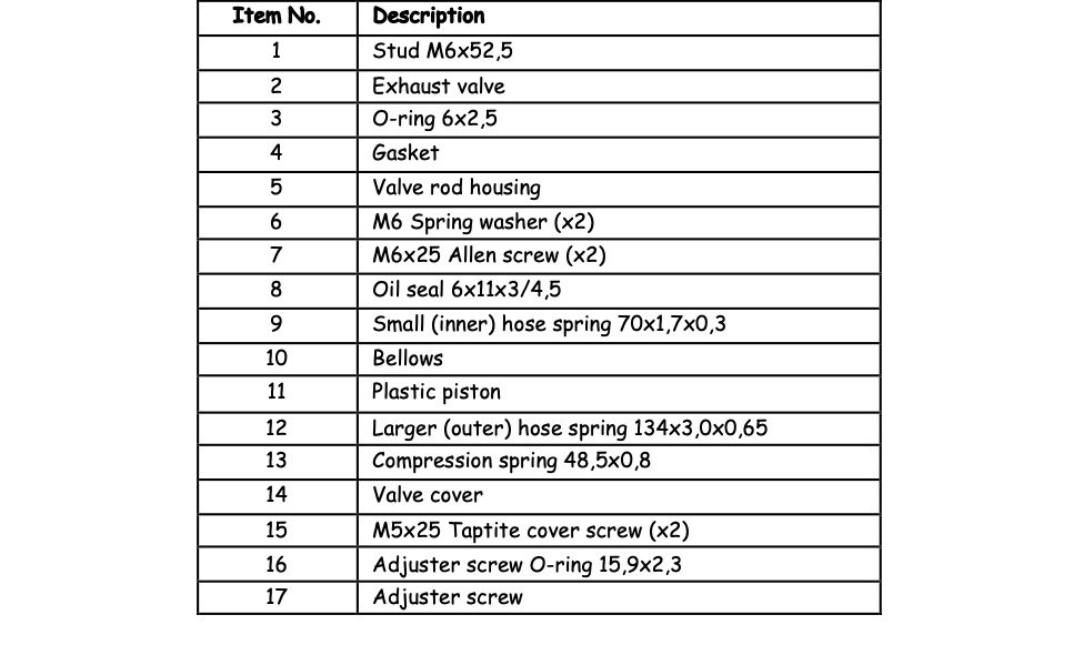

PV, magnetic & one-way valve / Location of magnetic valve / Hose connection to PV
Removal & stripping of the power valve
Should you only wish to do a quick check for free movement of the PV, you only need to complete steps 2, 3 and possibly 4 described below.
If you wish to do a 100% tear-down of the PV, then follow all the steps below. Alternatively, you may choose not to completely strip everything apart e.g. not removing the stud from the exhaust valve, etc., but that is entirely up to you.
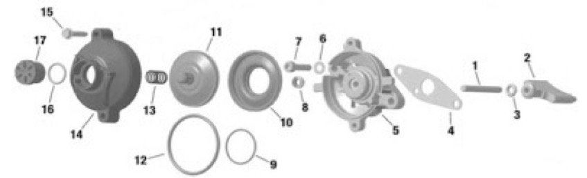
Remove the hose connection to the PV, release the adjuster screw (item 17) and the O-ring (item 16).
Remove the two Taptite screws (item 15) and carefully lift off the valve cover (item 14) and the compression spring (item 13).
Check for free movement of the exhaust valve by gripping the upper hexagonal end of the plastic piston (item 11) with your fingers and moving it up and down. If it is sticky, then proceed to the next step.
Using an Allen key, remove the two sets of Allen screws and washers (items 6 & 7) to release the valve rod housing (item 5) plus the exhaust valve, stud, gasket and O-ring (items 1 thru’ 4) from the cylinder. This allows you to move the whole of the housing and the exhaust valve to a slightly different position to possibly free up the movement. Align the screw holes, hold the housing with one hand and check for free movement of the valve with the other. If all is OK, then refit the Allen screws and washers, tighten up and re-check for free movement of the valve. If this doesn’t work, then the whole assembly may be removed from the cylinder to check for carbon deposits on the blade of the valve and to clean them off before refitting.
Prize off the outer hose spring (item 12) using the jaws of an open ended spanner or similar tool being careful not to damage the rubber bellows.
Unscrew the plastic piston (item 11) using a 10mm spanner, remove it, and slide out the valve, stud and O-ring.
Lift the bellows (item 10) to gain access to its underside, and gently prize off the bellows complete with the inner hose spring. For a complete strip down, items 1 thru’ 4 can then be disassembled. The oil seal (item 8) can be removed from the valve rod housing by careful use of the end of an Allen key or a suitably sized rod which is pushed in from the underside of the housing.
Cleaning and inspection
Firstly clean off all oil deposits, etc. from the parts that were removed using your personal choice of cleaning fluid – brake or carb cleaner works fine on these small parts. If there are any carbon deposits on the exhaust valve or other items, then these need to be removed as well, and a Scotch-Brite pad or fine steel wool works a treat but keep them well away from any of the rubber components.

Then, check for any carbon deposits inside the slot of the cylinder that the exhaust valve fits into and remove them if present ensuring that they don’t fall into the engine itself. Also check that the impulse bore on the cylinder is free of carbon deposits (refer arrow in the picture). Inspect the bellows for any cracks, holes, etc. and replace if necessary. Similarly, check that there are no cracks or damage due to overheating on the plastic piston - if there is any damage it will also require replacement. Inspect the plastic valve cover to check for damage. Once everything is cleaned up, you are ready for re-assembly.
Re-assembly
Should you have removed the stud from the valve blade, then it needs to be refitted. Apply a drop or two of Loctite onto the end of stud, screw it into the rear end of the valve blade. Before the Loctite dries off, set the overall length from the deepest part of the curve in the blade to the rear of the stud to give a reading of 72,0±0,3mm as shown in the picture. Check this dimension anyway even if the stud wasn’t removed and adjust if required. Remove any excess Loctite and re-fit the O‑ring onto the stud. Should you wish to check the measurement with the plastic piston fitted to the end of the stud, then the Vernier reading should increase to 81,6±0,3mm.

Lightly oil the blade of the exhaust valve and the O-ring and lower it into the slot in the cylinder ensuring that it is facing the correct direction viz. that the chamfer on the curve of the blade (as highlighted with the red arrow above) is facing downwards towards the bottom of the engine, and then test that it moves freely within the slot. Lightly oil and fit a new gasket ensuring that the impulse bore isn’t covered and that it doesn’t in any way impede movement of the exhaust valve – areas of concern are ringed in red in the picture on the right (above).
If the oil seal was removed from the valve rod housing, either refit the old one if it is still in good condition or fit a new one – in either event, apply some oil to the seal to aid fitment. Then, slide the housing over the stud of the valve and refit the housing onto the cylinder with the two sets of Allen screws and washers. Check along the way that the exhaust valve still moves freely before the screws are fully tightened.
Fit the inner hose spring onto the underside of the bellows, lightly oil the protrusion in the valve rod housing, and ease the assembly over the protrusion. Ensure that the bead on the bellows fits snugly into the groove all the way round – using a small Allen key with a rounded-off end so it doesn’t damage the bellows from the upper side of the bellows will help to ease the spring into the groove of the protrusion. Fit the plastic piston and nip it up with a 10mm spanner. Ensure that the bellows is properly in place all the way over the sides of the piston ‑ once again use the Allen key or a small flat screwdriver as an aide being careful not to puncture the bellows.
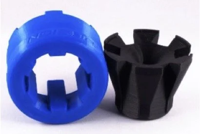
Next, you have to fit the outer hose spring around the bellows and the plastic piston. This can be accomplished with the aid of a special Rotax tool shown in the picture, or you could do it with the aid of two cable ties loosely fitted around the spring – using your fingers inside the loops you created will allow you to stretch the spring over the bellows. Once everything is in place, cut the cable ties and remove them. Then re-check the operation of the exhaust valve to ensure it is able to move up and down freely. Some final adjustments on the Allen screws and/or slight rotation of the valve assembly inside the cylinder slot using the 10mm spanner on the end of the plastic piston may be necessary to ensure complete free movement. Don’t forget to retighten the Allen screws.
Once all the above is in place, fit the compression spring plus valve cover and tighten into place with the two Taptite screws. Fit the adjuster screw and its O-ring into the valve cover and tighten down. As long as the O-ring is properly nipped, the actual tightness of the adjuster screw is not all that important and won’t affect engine performance, unlike the pre-EVO version where it was used to adjust the rpm setting of the PV. Lastly, refit the neoprene pipe connecting the magnetic valve to the nipple on the side of the valve rod housing.
Maintenance intervals & summary
To ensure you remain competitive, it is suggested that as a minimum you check that the PV is moving completely freely at the start of every race day. This can be done simply by removing the cover and compression spring and testing by gripping with your finger and thumb at the end of the piston’s hexagon. A complete strip down of the PV should be done at intervals not exceeding 3-months.
One of the major advantages of the PV used on the EVO engines is that it is unaffected by external conditions such as atmospheric conditions, jetting, condition of the matting inside the exhaust, etc. as was the case with the pre-EVO valves. Its operation is totally controlled by the ECU and therefore the rpm that it kicks in or out at is totally predictable and repeatable. There is a choice of two rpm that one can choose to have the PV activate or de-activate. Which of these you decide to use on any given track should ultimately be decided by the stopwatch – it’s the one single thing that doesn’t lie and pander to your ego.
Emile McGregor - MSA Technical Consultant