
The Dellorto carburettor.
Functions of the carburettor
There are many pre-requisites for a kart’s engine to function at peak performance, not least of which is the carburettor (the carb). So what exactly are its main functions? Well firstly, it needs to thoroughly atomize the fuel into droplets and mix them into the incoming airstream because we want a constant air/fuel ratio (A/F ratio) present in the combustion chamber. This process is something that we have no control over because it all has to do with the basic design of the carb itself, so we’ll leave that aspect up to the ‘pointy heads’ employed by the carb manufacturer. The commercial pump fuel that we use in karting can be ignited by the spark plug and burnt in the combustion chamber when the A/F ratio is as low as 7:1 (very rich mixture) all the way up to 20:1 (extremely lean), and the ideal ratio is in the region of 14,7:1 as this ensures complete combustion and also where we get the best utilization of the chemical energy present in the fuel. This ratio is measured on a ‘mass’ basis (not a volume basis) i.e. ideally one needs 14,7kg of air for 1kg of fuel. In layman’s terms, it means the engine sucks in roughly 9,000 litres of air for every 1 litre of fuel burnt – that’s a heck of a lot of air, and also explains why an engine is often likened to an air pump.
Its second function is to control the amount of mixture flow into the engine based on the position of the throttle pedal which is controlled by the driver according to his/her needs at any given moment. This is achieved by varying the cross sectional area of the carb’s throat thus altering the amount of mixture that is delivered to the engine. It achieves this by making use of a variable ‘restrictor’ in the throat of the carb which usually takes the form of a vertical slide, or a rotating flap known as a butterfly. The Rok OKJ uses a Dellorto VHSH 30 in South Africa. Overseas, both the Rok OKJ and DVS series use a 24mm Ibea carb with a butterfly, and hence will not be discussed in further detail.
Principle of operation
Because of the slight reduction of area within the throat of the carb, the air flowing through it is constricted and hence the pressure at that point is marginally less than atmospheric pressure i.e. a slight vacuum. Referring to the diagram below, we can see that a small quantity of the incoming air is bled off from the main flow and directed to the emulsion tube.

Fuel within the carb bowl is metered via a main jet before being fed into the emulsion tube, where it is ‘emulsified’ with the air bleed. The dictionary defines emulsion as being a fine dispersion of minute droplets of one liquid (the fuel) in another (the air) in which it is not soluble. Because the emulsion tube (or jet) is located inside the throat of the carb where there is a partial vacuum, then as air is drawn through the throat, the air stream is also able to draw a controlled rate of atomized fuel along with it before it is sent on its way to the engine.
Float bowl & needle valve
Imagine for a moment that the carb bowl is likened to an underground well, the pump that brings the water to the surface is the slight vacuum in the throat of the carb, and the hosepipe is the emulsion jet in the carb throat. There is a constant flow of water out of the hosepipe, but as ‘day zero’ approached and the water table dropped within the well, what happened was that the flow out of the hosepipe reduced. To prevent this from happening we need to keep the well level constant and this is accomplished as follows.
Firstly, there needs to be an inflow of fuel to the carb bowl to replenish what is being consumed by the engine - this is the job of the fuel pump, or in the case of the Comer engine for the Bambino class, a gravity feed from the fuel tank located higher than the carb bowl. Secondly, the level inside the bowl needs to be kept constant in order to ensure a constant A/F ratio – this is the job of the float/s plus a valve attached to it. If we didn’t have this float valve (a.k.a. needle valve) then the fuel pump, or gravity in the case of the Comer, would overfill the carb bowl because either of these is capable of delivering far more fuel than the engine can consume.
Control of fuel level
The float in the carb bowl can be likened to a boat in a small tank of water just bigger than the boat itself. The heavier the boat, the deeper it sits in the water plus the water level in the tank also rises, until a state of buoyancy is reached. Obviously the converse is true for a lighter boat. Having a heavier float within the carb bowl means the fuel level will rise, and this effectively results in a richer mixture being delivered to the engine (assuming the same throttle opening and no change in jetting). The float is allowed to pivot on a metal arm, and the position of this arm at any given time dictates how open or closed the needle valve will be. The needle valve, sometimes referred to as a needle & seat, has a conical tip at one end of the needle that allows it to seat against a similar shape thus forming a seal when fully closed. In many cases the needle portion is fitted with a rubber tip to enhance this seal.
So now we can appreciate that the level of fuel within the carb bowl is controlled by both the mass of the float and also the ‘height’ of the arm on which it pivots. The mass of the float (some carbs have dual floats) is strictly controlled by the class regulations laid down in the technical regulations, but there is usually a small tolerance allowed on the arm height when the needle valve is in its closed position.
Control of the fuel quantity
The amount of fuel delivered to the engine is dictated by the driver via the position of the throttle pedal. As the throttle is depressed, a cable linking it to the carb slide will either raise of lower the position of this slide within the carb throat. Attached to the lower end of the slide is a shaped tapered needle (not used on Bambino) that will then be raised or lowered within the emulsion tube. As this occurs, the area that the fuel can flow through is increased or decreased, thus altering the rate of fuel supplied to the engine. At the same time, the amount of air flowing through the carb throat correspondingly increases or decreases and hence the A/F ratio remains constant during the process.
Circuits within the carb
There are a number of ‘circuits’ within the carb that control the mixture to the engine during the various stages of its operation. The three circuits found on most carbs are the idle circuit, the progression circuit, and the main circuit. For simplicity, one can say that the idle circuit is the one that comes into play up until the throttle is about 1/8th open. During this phase, the engine requires a richer mixture and hence more fuel is added to the mix via this circuit. Without it, the engine wouldn’t idle and would probably stall due to insufficient fuel being available. The progression circuit comes into effect when the throttle opening exceeds 1/8th open, and stays in play until it is about ½ way open. At openings beyond this all the way up to full throttle, the main circuit is the one that rules the roost but the others remain in play.
Each of the first two circuits contains a jet or two within it. However, because the technical regulations dictate that those jet sizes are ‘fixed’, we won’t bother discussing them any further. The main circuit essentially comprises the main jet itself, the tapered needle, and the emulsion tube. Note that only the main jet is usually allowed to be altered to what you decide to be the best for your particular setup. Although the tapered needle cannot be changed, one is also allowed to alter its position within the emulsion tube by changing the ‘clip’ location at its upper end – this alters the area available for fuel to pass within the annulus created between the emulsion tube and the needle, thus making the mixture richer or leaner.
Tapered needle & clip

The diagram above shows an enlarged view of the upper portion of the tapered needle. There are 5 grooves that are machined into the needle, and the clip can be fitted to any of these to marginally alter the mixture. Insertion of the clip into groove 1 which is uppermost on the needle will lean out the mixture, whilst in groove 5 it will provide a richer one. For various applications e.g. road bikes, scramblers, karts, etc., Dellorto make a range of needles that are in excess of 200 different shapes. The length and shape of the tapers determines how much flow is delivered to the engine at various throttle openings. Luckily, all the guesswork is taken out of this as we are only allowed to use three of the many on offer.
Mixture screws
Mixture screws are used to marginally alter an additional amount of either the fuel or air being fed to the engine. Dellorto usually adopt the principle of where this screw is located w.r.t. the slide, to dictate whether it adjusts the fuel or the air – their convention is that upstream = air screw, and downstream = fuel screw. If the mixture screw is located downstream of the slide, it is used to adjust the fuel, so screwing it inwards (clockwise) will lean out the mixture and vice-versa. If the mixture screw is located upstream of the slide it controls the air, so screwing it inwards (clockwise) will have the exactly opposite effect to a fuel screw and will richen the mixture.

One can also visually tell the difference between the two types of screws by examining the tip of the screw itself. Referring to the picture above, notice that the air screws shown have a fairly fine point on their tips, whilst the fuel screws have rather stubby tips. Although either of these mixture screws remain in operation over the whole rev range, their primary function is for use in conjunction with the throttle screw to obtain the best mixture setting for the engine whilst it is idling.
Bambino (Dellorto SHA 14-12L)

The SHA 14-12L is a very simple carb that is used for the Bambino class and is shown in the picture on the RHS. The carb doesn’t have a tapered needle and relies solely on supplying varying amounts of mixture to the engine by movement of the slide vertically within the throat of the carb. Looking down the throat of the carburettor, one will see the emulsion tube which is located directly in the path of the incoming air. The carb has a single ‘donut’ shaped float with a mass of 3,5g and the choice of main jet is free. These jets have a thread at one end that is M5x0,75 and access to the float, main jet and needle valve is gained after removal of the float bowl at the lower end of the carb. The carb also has an idle adjusting screw as indicated. Turning the screw inwards simply lifts the slide by a small amount thus allowing more mixture to enter the engine and results in a higher idle rpm.
Kid-Rok and Mini-Rok (Dellorto PHBG 18 BS)
This carb shown above has a dual set of floats, each with a mass of 4,0g and the choice of main jet is free within certain parameters. For Kid-Rok the main jet might be controlled (refer latest regulations), but free choice is usually allowed in Mini-Rok’. These jets have a thread at one end that is M5x0,75 (as for the SHA 14-12L carb) and access to the floats, main jet and needle valve is gained after removal of the float bowl at the lower end of the carb. The tapered needle fitted to the slide is specified in the regulations and must be a W23 for either class. The clip position has been changed to free, but confirm with the latest regulations and/or bulletins. The carb also has a throttle screw as well as a mixture adjusting screw as indicated. As outlined earlier, this is a fuel screw. As a starting point, the mixture screw can be turned out by 1,5-turns.
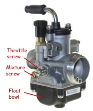
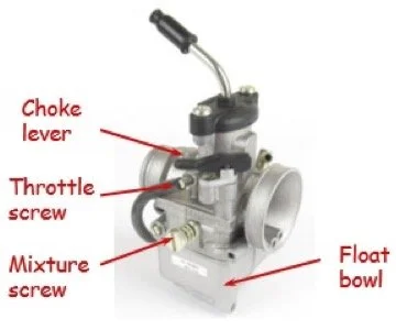
Rok OKJ (Dellorto VHST 24 BS)
This carb, shown in the picture overleaf, has a dual set of floats, each with a mass of 4,0g and the choice of main jet is free. These jets have a thread at one end that is M6x0,75 (different to all the previous carbs discussed) and access to the floats, main jet and needle valve is gained after removal of the float bowl at the lower end of the carb.
If one only requires access to the main jet, this is achievable when removing the large nut on the lower end of the float bowl. The tapered needle fitted to the slide is specified in the regulations and must be a D55, with the clip position being free. The carb has a throttle screw as well as a mixture adjusting screw as indicated. As outlined earlier, this is an air screw. As a starting point, the mixture screw can be turned out by 1,5-turns. Additionally, a choke lever is fitted to aid in push starting when conditions are cold.
Rotax (Dellorto VHSB 34 XS)
All the Rotax classes make use of the same carb. It has a dual set of floats, each with a mass of 4,0g and the choice of main jet is totally free. These jets have a thread at one end that is M6x0,75 and access to the floats, main jet and needle valve is gained after removal of the float bowl at the lower end of the carb. If one only requires access to the main jet, on some of the carbs this is also achievable by removal of the large nut on the lower end of the float bowl. The tapered needle fitted to the slide is specified in the regulations and must be a K57 for all classes, but the clip position is free.
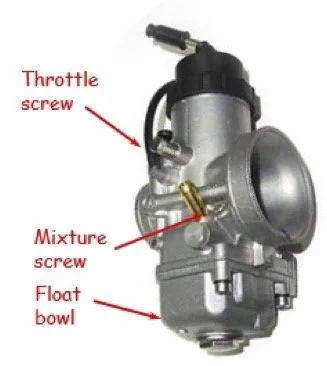
The carb also has a throttle screw as well as a mixture adjusting screw as indicated on a previous picture. As outlined earlier, because of its location upstream of the slide, this is an air screw. The carb insert, also known as the venturi and accessed by removal of the slide, must be stamped 12,5 as shown in the picture below to comply with the regulations. The 12,5 refers to the size of the progression hole in the top of the insert which is actually 1,25mm in diameter. Note that there are two holes on the top of the insert, and the progression hole is the larger of these. As a starting point, the mixture screw can be turned out by 1,5-turns.

Throttle body restrictors as shown above are mandatory on both Micro- and Mini-Max, and these plastic inserts reduce the available flow area within the carb throat to 35mm tall x 18mm wide.
Carb designations
You may well have wondered what the designation on the various carbs indicate, so here is a guide to understanding this. The number one sees in the designation is the bore or venturi size of the carb i.e. 34 = 34mm diameter, and 14-12 would mean that it has a bore of 14mm which reduces to 12mm at the venturi section. The next two letters that precede the number describe how the air is regulated and also the direction of air flow. So, the ‘S’ on the Bambino carb denotes the flow is controlled with a simple Slide with no needle, ‘P’ indicates that a Piston with needle is used, whilst ‘V’ means that a flat Valve with needle does the job. In all of these carbs, the ‘H’ denotes that the air flow is Horizontal (vertical or downdraught carbs would use R instead of H).
Lastly, there are either one or two letters after the size of the carb. Apart from the Bambino carb, one will see either a ‘S’ or a ‘D’ as part of the designation. These refer to which side of the carb the adjustment screws are located on when viewed from the incoming air side. Here, the ‘S’ denotes Sinistra (left in Italian), and ‘D’ would be for Destra (right in Italian). Other letters such as ‘L’, ‘B’ or ‘X’ also appear in the designations. The ‘L’ means that the engine side fixing uses a clamp attachment, ‘B’ means the fixing to the engine is via a spigot with a rubber sleeve, and ‘X’ indicates that the carb is specifically for Rotax.
Setting of the float arm
On the VHSB 34 carb used on all Rotax classes, adjustment of the float arm height is accomplished using a special gauge (Rotax 277400) available from the distributor. When conducting this measurement, the carb body must be inverted and the gasket of the float bowl must also be removed. The arms of the float lever will then be resting horizontal under their own weight. The gauge is then slid across the bottom face of the carb and both of the arms must lie within the slot of the gauge.

For the PHBG 18 carb used on Kid-Rok and Mini-Rok, no mention is made in the regulations of what the float arm height should be (measured between the body of the carb to the top side of the arm whilst the carb is inverted), but the ideal setting is 16 ±0,5mm as shown in the picture on the RHS.
Technical infringements
Upon inspection by the Scrutineers, any deviations from any of the items laid down in the regulations for the class concerned are regarded as technical infringements. The carburettor is not an item which is sealed by the engine builder because the competitor needs to be able to gain access to its innards to make changes to jetting, etc. as race day proceeds. The Competitor or his Entrant are therefore wholly responsible for any infringements found to be present at the time of inspection. As laid down in the regulations, the penalty for this is exclusion, so make 100% sure that your carb is compliant at all times.
Air/fuel ratio and performance
As mentioned earlier, an A/F ratio of 14,7:1 for petrol (also referred to as a Stoichiometric mixture) is where we get complete combustion. However, the best fuel consumption is when you have a lean mixture, and best power is made when you are running a slightly richer mixture than the 14,7 figure mentioned. The ‘actual’ A/F ratio compared to the ‘ideal’ A/F ratio is often referred to as ‘lambda’ (denoted by a Greek L = λ). So, as an example if you were running a richer mixture of say 13,5:1 then
λ = 13,5 ÷ 14,7 = 0,92
When one puts more fuel into the cylinder at high engine load and speed, it cools down the combustion chamber (through fuel evaporation and heat absorption) which in turn allows the engine to produce maximum torque i.e. maximum power. This is shown graphically in the drawing below.

Emile McGregor - MSA Technical Consultant