
Mixture flow through the engine
To understand the mixture flow through a 2-stroke engine, one needs to examine this by starting at the air-box, through the carburettor, the inlet port, crankcase, transfer ports, the compression and expansion strokes, and finally the discharge of the spent exhaust gases via the exhaust port and exhaust system. This chapter is intended to provide a general overview and better understanding of some of these components without the need for going into any hard core engineering or physics that is involved.
Air-box and carburettor
The air-box is worth a mention, for two basic reasons. On a kart, the inlet to the carburettor invariably faces the incoming airstream. At high speeds, this can be likened to force feeding the engine with air, so the air-box is used to iron out these variations. Secondly, it houses the intake filter mat whose job is to trap any large particles (dust/sand, etc.) that could enter the small passages within the carburettor and/or the engine itself, thus potentially causing irreparable damage to one or both of them.
In simple terms, a float bowl carburettor, which is what we have on a kart, relies on the laws of physics to make it work. It relies on the principle that the faster the air moves through a duct, the lower its static pressure will be. The air is made to move faster through the body of the carb by a slight narrowing of the passage, but mainly due to the throttle slide which restricts the passageway dramatically, especially at small throttle openings. This lower pressure causes a small vacuum which then draws fuel from the carb bowl into the passageway as shown in the cross sectional sketch.

The fuel then mixes with the incoming air and the air/fuel mixture proceeds on its way into the engine. When the accelerator is depressed the throttle slide rises, so to compensate for the reduced vacuum we have a tapered needle, as shown in the sketch, attached to the slide that in turn moves vertically within a jet. As this tapered needle rises, the area created between the jet and the needle is increased, which in turn allows more fuel to enter the carb to be mixed with the incoming air stream. As the fuel inside the bowl is used up, it needs to be replenished by the fuel pump. Obviously the level of the fuel inside the bowl is fairly critical and needs to be maintained at a constant level for correct operation of the engine throughout the rev range. This is the job of the float/s plus a rubber tipped needle jet that it opens or closes to suit, and hence the name ‘float bowl carburettor’.
Various needles are available for the Dellorto carb which is the one commonly used on karts. Up to 5 of their dimensions can be varied, thus altering their performance i.e. leaner or richer than a counterpart, at varying throttle openings. Once again, the needle designation e.g. K57, W23, etc. are mandated in the technical regulations for the various classes and may not be tampered with. That said, one is (usually) free to alter the clip position at the top of the needle, and this change makes the needle either richer or leaner at any given throttle slide position.

Two-stroke cycle
In order to properly understand the rest of the chapter, one needs to appreciate when the various ports open and close in the two-stroke cycle (refer also to the port timing diagram shown later). There are three types of ports in a two-stroke engine viz. the inlet port, the transfer port, and the exhaust port. Note that there could be more than one of each of these types arranged around the wall of the cylinder and if there are multiples of any type, they will usually be a mirror image of each other. The location of these ports height-wise in the cylinder determines the opening and closing of the relevant port with respect to top dead centre (TDC) i.e. the port timing on the engine. Various phases of the two-stroke cycle are shown in the diagram below.

Stroke 1 - Induction & Compression ::: Stroke 2 - Ignition and Exhaust
Piston port control
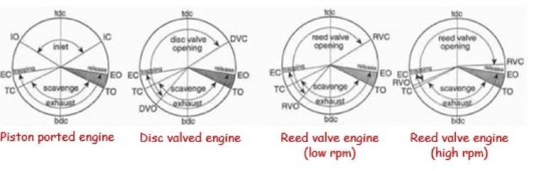
Because the ports are usually located in the cylinder itself, it may be appreciated that the port opening and closing angles a.k.a. the port timing in degrees, will be symmetrical around top dead centre (TDC) for the inlet port, or bottom dead centre (BDC) in the case of the transfer and exhaust port. As an example, if the exhaust duration is 150deg, then it will open 75deg before BDC and close 75deg after BDC. This form of timing is known as piston port control and can be used on the inlet, transfer and exhaust ports.
Piston port controlled inlet
Piston controlled inlet ports have the advantage of simplicity, but are handicapped to some extent as next explained. This type of intake system is generally used on engines producing a relatively small power output, and examples in the karting environment are the C50 Comer, Kid Rok and Mini Rok engines. The rising piston creates a lower than atmospheric pressure within the crankcase once the inlet port starts to be exposed by the piston skirt, and consequently the air/fuel mixture rushes down the inlet tract to fill the crankcase. However, at TDC the port is still open, so as the piston descends, air/fuel mixture will want to be pushed out of the crankcase and back through the open inlet port. At low speeds a small amount of fuel charge is lost, but at higher engine speeds there is usually less loss of mixture as the combined force of pressure waves and the inertia of the high velocity mixture is stronger than the pressure created in the crankcase by the descending piston.
Disc valve controlled inlet
Disc valve control can only be applied to the inlet system, and the inlet port is now re-located in the crankcase. The port, which is machined in the same axial orientation as the crankshaft, is opened and closed by means of a segmented disc that is attached to the crankshaft and rotates with it. The opening and closing angles on the disc now no longer need to be symmetrical around TDC, and this allows the engine manufacturer more latitude with the design. This type of control is still used on many motorcycles but not on karts, and hence will not be discussed any further.
Reed valve controlled inlet
Lastly, one has reed valve control which is used, for example, on all Rotax kart engines. The reed block assembly is situated between the carb and the inlet port which can be located in either the cylinder, or the crankcase itself.
The Rotax reed block assembly is shown as Item 1 in the diagram, and Item 4 is the inlet tract to which the carb is attached. For Rotax kart engines, the reed block assembly fits directly into the side of the cylinder as shown below.

The reeds (Item 2) sit against the face of reed block and act as a one-way valve, thus preventing blowback of the air/fuel mixture into the inlet tract. Low rpm cylinder filling improves and, because the air only passes through the carb once, the air/fuel ratio remains correct, which in turn translates into good low speed combustion. Reed valves are not entirely problem free – the petals need to be made of relatively thin material so that they are flexible at low rpm and don’t restrict the flow, but at higher rpm they need to be a lot stiffer so that they don’t flutter.
Without going into detail, suffice to say that the inlet timing is no longer symmetrical around TDC for a reed valve controlled inlet, and the timing also alters as the rpm increases. A comparison between the three types of port control is shown in the diagram below.
Exhaust port and power valve
The width of any port, but more importantly the exhaust port, is limited by certain factors and the most worrying one is ring breakage. To overcome the problem of providing sufficient time for the exhaust gases to escape, the height of the port could be increased. This however does alter the mid-range power of the engine, so to overcome the problem, some manufacturers make use of what is known as a power valve. These come in variety of different designs for example a rotating barrel style, or a simple blade style such as the Rotax one shown. In the case of the Rotax valve, at low revs the blade is held in the depressed position by a spring and when a pre-set rev limit is attained, it is released into the upward position pneumatically.

At low rpm the overall height of the port is restricted by the blade of the valve which is the same width as the exhaust port. When the valve kicks in at somewhere around 7,500rpm (valid on older engines, but at higher rpm on EVO versions), the blade is pulled back, the exhaust port timing is altered because the port height is effectively increased, and this extends the mid-range power band of the engine. Alteration of the rpm at which it opens/closes has an impact on the overall power output graph typically as shown below.

Exhaust system
A 2-stroke 125cc engine with a simple straight pipe as the exhaust system can only burn roughly 125cc of air/fuel mix. However, the same engine with good tuned exhaust system can combust closer to 180cc of air/fuel mix. The reason for this is that a properly designed exhaust system makes use of the pressure waves emanating from the combustion chamber to effectively supercharge the engine. So how does this work?
Think of an engine's exhaust port as being a sound generator. On every stroke when the piston uncovers the exhaust port, a positive pressure pulse of exhaust gases (higher than atmospheric pressure) rushes out of the port and down the exhaust pipe. This pressure pulse travels at the speed of sound whilst the exhaust gases are travelling at a much slower speed. To understand this, use the analogy of a rock thrown into a river – wave ripples are formed and these travel much faster than the water itself. When this positive pressure pulse reaches the open end of the pipe, the laws of physics dictate that a much weaker, but negative pulse (lower than atmospheric pressure) is created which returns back up the exhaust pipe at the speed of sound. If this negative wave can be timed to arrive at the exhaust port before it closes, it can help suck spent exhaust gases out of the cylinder. However, there is only a small rpm range where this can work effectively - at high revs, the piston would have travelled too far up the cylinder thus closing the exhaust port and the negative wave is of no use, and at low revs it would have arrived too early to do any good.
This phenomenon was first discovered in the 1950’s. Following this, it was realised that these pressure waves could be further improved by using a divergent cone to increase the strength of the negative wave i.e. creating a bigger ‘suck’ at the exhaust port to empty the cylinder of spent exhaust gases. In doing so, one must realize that this sucking action not only draws out the spent gases, but also ends up pulling some excess unburnt air/fuel mixture into the exhaust pipe with the proviso that the transfer ports are still open. It was then discovered that adding a convergent cone downstream of the divergent section could increase power still further. The rationale is that the convergent cone generates a positive pulse that returns back towards the exhaust port, and this can be used to effectively ‘stuff’ some of the unburnt air/fuel mix back into the cylinder before the piston skirt closes off the exhaust port i.e. we’ve now created a supercharged engine.
In practice, the exhaust system commences at the entrance of the exhaust port and ends where the gases finally meet the open atmosphere at the end of what is commonly known as the stinger. It is comprised of a number of different pipe sections which are known as the header, diffuser, sometimes a parallel portion, a baffle and a stinger. The header, diffuser and baffle sections may be parallel, divergent or convergent as shown in the diagram below. Furthermore, each of these sections may consist of a number of stages with different angles such as the three stage one shown on the diffuser. Suffice to say that, up to a point, multi-staging of the header and diffuser tend to increase the amount of ‘suck’ provided. Similarly, multi-staging on the baffle will tend to increase the amount of ‘stuff’ provided.

Typical Exhaust Layout
The diameters, angles and lengths of the individual portions of the system are selected by the engine manufacturer to suit the application of the engine. For a kart, one is generally attempting to derive the most power from the engine whilst also retaining as wide a torque band as possible within the operating rev range to provide good acceleration. This is of even more importance on a fixed ratio non-gearbox kart as one doesn’t have the luxury of being able to keep the engine revs at the best point for optimum performance. Altering any of the abovementioned parameters of the system affects the torque and consequently the power output of the engine. Don’t even think about experimenting with them because for each of the classes there are laid down dimensions to which the exhaust must conform to, and non-compliance results in exclusion.
Emile McGregor - MSA Technical Consultant