
Caster & camber adjusters
Important front end angles
An imaginary line joining the centres of the two large holes in the steering yokes or C’s (refer picture on RHS) that are welded to either side of the chassis, determines what is known as the caster angle and the kingpin inclination angle. Both of these are angles which are measured off the vertical and are shown in the diagram below.

When viewed from the side, altering the kingpin angle closer to the vertical will provide less caster, and increasing the angle will give more caster. Because the stub axle and its boss which houses the kingpin are a solid unit, then looking from the front and altering the kingpin inclination will by implication change the angle of the stub axle to the horizontal and hence alter the camber i.e. whether the tyres lean inwards off the vertical (known as negative camber), or outwards (known as positive camber).
Another important angle on the front end is known as toe. The toe can be either positive (tyres are pointing outwards in the direction of travel when viewed from above) or negative (tyres are pointing inwards). On cars, the convention is to measure this in degrees, but on karts it is more usual to state it in millimetre per side. This is adjusted using the tie rods that connect the steering column to the spindles on either side of the kart. The length of the rods, which are fitted with a Rose joint at either end, can be increased or decreased to suit the setting required. The Rose joints are fitted with a RH and LH thread plus a locking nut at opposite ends that facilitates the adjustment and also locks it into place.

The final angle that concerns us on the front end is the Ackermann angle - this gives rise to what is known as Ackermann steering. Ackermann is the angle measured between the fore/aft direction through the kingpin, and the line joining the kingpin to the attachment point of the tie rod to the spindle. As may be seen in the diagram on the RHS, this can be modified marginally by using hole 1 or hole 2. Some spindles are equipped with only one hole but most have two holes, and sometimes even three. Using the innermost hole (to the kart’s centreline) increases the Ackermann, and vice versa. Ackermann is responsible for allowing the outer wheel to turn through a lesser angle than the inner wheel, and makes life a whole lot easier when negotiating a corner, and increasing the Ackermann will result in a quicker response when turning into the corner.
Kingpin movement
The holes in the yokes are usually 22mm diameter, and the angle at which they were bored by the chassis manufacturer determines the basic front end settings. You don’t really need to know these initial angles, but note they also vary somewhat between manufacturers. Suffice to say that the camber is generally in the region of 14 to 20 degrees and the kingpin inclination is somewhat less. What you will notice on your kart is that these 22mm holes in the yokes are not easily visible because they have an adjustment mechanism fitted to them which obscures the hole. The kingpin bolt is either 8mm on smaller karts, or 10mm for the more senior chassis. The adjuster has an eccentric hole to accommodate the kingpin bolt as well as a centralized raised boss which locates it into the fixed 22mm hole in the yoke. By rotating the adjuster within the yoke, the location of the kingpin hole and the raised boss to each other are altered, thereby changing the caster and camber on the kart.
Imagine for a moment a vertical rod that is held in a bush at either end. If the lower end is not allowed to move in any direction, and let’s say the upper end is moved sideways (referred to as a ‘translation’ in engineering terms), then the rod effectively becomes jammed in both the lower and upper bushes. To prevent this from happening, one needs to allow the bushes to angle themselves and stay in line with the rod axis whilst this translation takes place. This is accomplished by the use of spherical surfaces within the adjuster which is made up of a number of components as shown in the diagram on the RHS for the two basic types of adjusters available on a kart. It is thus important to note that these surfaces must not be damaged in any way, and must be relatively free to move, otherwise the steering will want to bind up when adjustments are made.
Types of adjusters
The Type 1 adjuster shown and commonly referred to as a Sniper adjuster, is supplied on CRG and Praga chassis whilst the Type 2, or a Pill adjuster, is what the Birel, Haase, Intrepid, Kosmic, Parolin, Ricciardo, Tony and other chassis come with as standard. There are also after-market kits that allow one to change from a Pill to a Sniper system providing you have yokes that are sufficiently wide (approx. 40mm) and that have a 22mm bore.

On the Sniper system, the top yoke is fitted with the parts as shown in the picture above, whilst the bottom yoke has a ‘fixed’ hole – fixed in the sense that it isn’t adjusted, but it still contains a spherical component allowing free movement of the kingpin bolt in the fore/aft and also in/out directions when adjustments are made on the top half. The big advantage of the Sniper system is that it allows caster and camber adjustments to be made completely independently of each other. The upper portion containing the spherical depression is able to slide in/out along grooves on its underside that mate up with grooves on its base plate. When fitted to the yoke, these grooves should face directly across the width of the kart. Camber adjustments are made with the aid of the grub screws seen in the picture and the kingpin hole simply translates inwards or outwards in the process. To alter the caster, the kingpin bolt needs to be slackened off a fair amount thus allowing the upper portion with the spherical depression to be lifted upwards off its base plate and be repositioned into a groove that is either forward or backwards of the one in which it was - the grub screw settings remain unchanged in the process.
On karts fitted with a Pill adjuster, there is an eccentric Pill located on the top yoke as well as on the underside of the lower one. Referring to the picture on the RHS, these Pills have a number of holes around the periphery that are used to aid with the adjustment settings. Some older versions only had 4 holes, which then became 8, and now 20 holes to allow for even finer adjustments. Some chassis makes such as Haase also supply a 16 hole Pill. In all cases the kingpin hole is offset (or eccentric) to the Pill itself which has a boss on the underside to locate it in the centre of the bored hole in the yoke. When the arrow, shown ringed in the picture, is facing say 12 o’clock, then the hole for the kingpin is directly opposite at 6 o’clock i.e. furthest away from it. As a further example, if the arrow is the 2 o’clock position, the kingpin is at 8 o’clock, etc.

Regarding the amount of offset on the kingpin hole, the Pills are available from zero offset (the hole is completely centralized) all the way up to a reported total amount of 3° (more on this later) from its original position when you rotate the arrow through half a turn. The picture below shows a set of Pills that range from zero offset up to a reported 2,5° and one can tell the amount of offset by counting the ‘dots’ (shown ringed) on the Pill with every dot supposedly being equivalent to 0,5° i.e. a 4-dot Pill equates to 2° of total movement when fully rotated by a half turn. In this picture, the dots also replace where the arrow would have been located.

By judicious choice of Pills on the upper and lower yokes and having their arrows pointing in opposite directions on a fore/aft line, you are then able to nearly double the total angle change available when compared to that of a single Pill. This is mostly used for caster changes as alterations to the camber are usually small.
Unlike a Sniper adjuster where you can adjust caster and camber independently of each other, this is not the case with a Pill adjuster. Because of its inherent eccentric design, the kingpin hole on the Pill moves along a circular path when the Pill is rotated, and hence any change to the camber will also influence the caster and vice-versa.
Laser alignment tools
Any alterations you wish to make on the front end setup are best not done using your ‘Mk 1 eyeball’ plus a tape measure, and a variety of accurate laser alignment systems are available on the market. Sniper (made in the USA, and a popular choice for the majority of karters) is one of many, and their V2 system shown in the lower right picture takes a lot of the guesswork out of the process and are great for setting toe and camber. They each incorporate a laser that, when the units are mounted onto the stub axles, will point towards one another across the width of the kart and shine onto a graduated scale of the opposite unit. The spot where the laser dot ends up then indicates the toe and camber measurements in millimetres (more about this later).

Sniper V4 (LEFT) Sniper V2 (RIGHT)
Sniper also have a V4 system shown above left. Each of these units have two lasers – one that points across the kart for toe and camber as per the V2, and one that faces the rear of the kart. This extra laser can be used to check for any longitudinal twist that may be present in the chassis. It can also be used to check for crab, which is a condition where the front end of the chassis has been displaced laterally compared to the rear, due to a racing incident. In addition, Sniper can supply a V4 accessory kit that when used in conjunction with the V4 lasers, can provide you with an actual caster measurement. There is also a German company called Kartlaser that make a system similar to Sniper’s V4.
Placement of lasers
When making any adjustments with the aid of the lasers, it is extremely important that you are consistent with their placement. Each laser is fitted with a very powerful magnet at its lower end that is used to hold the unit in position onto the stub axle. The laser unit must be perfectly vertical to get a proper reading, and for this reason alone, you should never mount them onto the hubs because the hubs are free to rotate on the stub axles. Because hubs are available in different lengths and you may have changed them since last checking the front end, you can also never be perfectly sure the lasers are the same distance apart as they were the previous time you checked. Therefore, it is strongly recommended that you always place them on the stub axles – whether you choose to place them outboard where the axle is necked down for the thread, or inboard against the stepped portion close to the boss, is really immaterial as long as you always use the same placement position. Ideally, it should be chosen to be as close as possible to the middle of the width of the tyre or contact patch.
As mentioned earlier, the graduated marks on the lasers indicate toe and camber in millimetres, with each major block (refer picture on RHS) reportedly being equivalent to a 2mm movement for the axle being adjusted. As may be appreciated once you look at these blocks more carefully, they are a lot bigger than 2mm and are in fact 6mm in size - the reason for this is the multiplying factor caused by the distance between the two lasers.
The 0,5° and 2mm reported values mentioned previously are however not 100% correct as they are dependent on a number of factors viz. the width of the front end between the kingpins, the distance between the two lasers, and the height of the boss on the stub axles. Suffice to say that a 2mm movement of the dot on the lasers for a Bambino chassis will result in ~50% more ‘real world’ movement than on a DD2 chassis in terms of toe and camber settings for any given Pill. Similarly, rotation of this Pill through half a turn results in nearly double the angular change in caster on a Bambino compared to a DD2. The Junior and Senior chassis provide changes about midway between these values because their stub axle boss is shorter in height that that of a DD2.
For these reasons, it is extremely important to be consistent with the laser placement. Also, don’t get you knickers in a knot about the discrepancies mentioned in the ‘2mm’ divisions. What is important, is that for your kart you carry on making changes based on the laser readouts and not worry too much about what it happens to be in ‘real world’ terms for the toe and camber. There is a ‘cheat sheet’ presented later that you can use as a guide to make your life simpler when doing adjustments.
Checking toe and camber
Before one makes changes to the settings it is useful to know what is currently set on the kart to give you a baseline to work off. So, before we discuss how to make any major changes, let’s look into how you check the toe and camber settings you already have.
Firstly, set the kart up on its stand and remove the front wheels as well as the hubs if they are fitted. On a DD2 you will also need to lock the brakes to prevent them from rotating, and a cable tie between the foot pedal and a chassis tube can be used for this. Next, clean off the surface that you will be using to mount the lasers to and then fit them to the front end using the magnets to keep them in place. If you have a non-magnetic hub on your DD2, the lasers can also be held in place with a cable tie. Ensure that the lasers are located in your preferred position on the axle, align the steering wheel so it is centralized and then level the lasers with the aid of the built-in bubble. You need to constantly check this level as you proceed because small changes may occur along the way.
With the lasers switched on, observe where the dots are pointing onto the opposite laser’s scale. As the steering wheel might not have been 100% correctly centred earlier, you may need to make some minor adjustments to it so that you get the dots on either side showing an equal setting – remember to constantly check the level of the lasers. In the picture on the RHS, the position of the laser dot is indicating a toe-out of 2mm per side, and also a zero camber (each large block represents 2mm). Make a note of these settings.

Now, before you proceed with making any adjustments and although you can’t check the exact amount of camber you have with one of the more simplified lasers, you should at least check that you have equal caster per side. You do this by conducting a ‘sweep’ with the steering wheel as follows. Mount a steel ruler at a suitable central spot on the floor pan, forward of the steering column, as shown in the picture. Rather than holding the ruler in place by hand, use a magnet for this as you then also know that it is consistently in the same place whilst doing the test.

Rotate the steering wheel to the right until the laser dot crosses the ruler as shown in the picture, and make a note of the reading. Repeat by rotating the steering wheel to the left and compare the two readings. Ideally they should be identical, or at least within 2mm of each other. If the sweep readings are not the same, then either the caster on the one side is more than the other (the side with the dot highest on the ruler has the most caster), or your chassis has a twist that needs to checked out. If the chassis is not twisted, then every 4mm of difference is roughly equal to 1° of caster.
Remarks on making changes
Let’s start by stating that there are no hard and fast settings for your kart, and if one competitor runs settings of X, Y and Z on toe, camber and caster and does the best lap times, it doesn’t mean that you should also be using them. There are so many factors that influence what is the best for your kart and they include the make of chassis, what tyre pressures you are running, what hubs you have fitted, condition of the track, etc., etc., and the list just goes on and on. However, don’t despair because there are some good indicators you can use to guide you. The most important of course is driver feedback, followed by tyre temperatures immediately after the kart comes off the track, and also the tyre wear patterns. How these changes you are about to make will affect the handling of the kart have been dealt with in other chapters entitled ‘Kart Setup’ and ‘Tyre Setup’, so they will not be repeated here.
A word of warning - you should never make more than one change at a time otherwise you may well be shooting yourself in the foot. Making changes to the toe or Ackermann settings is a straight forward exercise and will not be discussed further (refer previously mentioned chapters). Altering the caster and camber is also pretty straight forward for those that have Sniper adjusters fitted. What confuses the heck out of most people however, is how to do adjustments with a Pill adjuster, so this will be discussed in a bit more detail.
Neutral-neutral
An important concept to grasp is that of neutral camber plus neutral caster. This might seem obvious to some, but not so for everyone. When your chassis, stub axles and yokes were designed and everything was then assembled, one of the objectives was to have the axles parallel with the track surface i.e. the wheels would be completely upright and have neutral (zero) camber. The other was to have a camber angle that the designer considered to be the most optimal i.e. when the kingpin was axially aligned with the holes in the yoke, and this is known as neutral camber. As mentioned earlier, this angle varies from one kart make to another and is also determined by factors such as the torsional rigidity of the chassis, but there is no need to concern yourself with them.
A neutral-neutral setup is easily adjusted when assembling a kart out of the box and that is supplied with Sniper adjusters. Each Sniper is simply assembled with an equal number of groves showing fore and aft to give neutral caster. The grub screws are adjusted so that the sliding portion is midway across its setting range, and when checked with the lasers, this should be very close to neutral camber with only minor adjustments being required.
For a kart with Pill adjusters, always start with the arrows pointing fore-aft. The top arrow (or dots) should be pointing rearwards, and the bottom one towards the front of the kart. The important point to grasp here is that to achieve neutral caster, you must use identical Pills both top and bottom (or as close as possible to this). The camber should then also be pretty close to neutral but may be a bit off, so we’ll discuss how to sort that out in the next section.
Adjustments to the Pill
Consider two identical old style Pills that only had 4 holes. There are 4² = 16 possible combinations of settings. As the number of holes increased, so did the available combinations, and with the 20-hole one now in common use, there are 400 possible combinations of camber and caster. Now add to this to the fact that you can mix ‘n match the upper and lower Pills e.g. a 2-dot combined with a 5-dot, and you end up with literally thousands of potential combinations.
You can’t be expected to deal with this, so you need to simplify matters. The easiest way to do this is to always use the upper Pill to change caster, and the lower one to alter camber, and the rationale is simple. You don’t change the camber much, so use the more difficult Pill for you to access i.e. the one at the bottom, for this. We know that the two settings are not really independent of each other, but using the following approach will get you pretty darn close. The following tables provide a ‘cheat sheet’ of approximate adjustments achieved on the various chassis sizes for both camber and caster.


The tables are valid as long as you start with both pills in a fore/aft direction and only use the bottom one for camber adjustments, and the top one for caster adjustments. If you use a mix ‘n match approach, you could as an example using the 1050 chassis table get ~1mm camber change with a 4 or 5-hole movement on a 2-dot Pill. However, you can get the same effect with a 2-hole movement on a 4-dot, or a 1-hole movement on a 6-dot Pill. It is always best to use the least amount of holes of rotation to get the camber correct because it has the least effect on the caster.
Method of approach
Let’s forget for the moment about toe and Ackermann settings as these will largely be determined by driver feedback on how the kart is handling. Then if you were starting from scratch, you should always commence with a neutral-neutral setting (or as close to this as possible) and get your camber setting correct. Make minor adjustments to the camber and tyre pressure settings until the tyre temperatures and wear patterns tell you are OK. This setting shouldn’t need to be changed too much unless the conditions change quite a bit.
You then try to find the most optimal setting for the caster. Remember that this is the setting you should be altering most frequently as it has a largest influence on how the kart will respond. It’s the one you should be altering if the track starts off as ‘green’ and then changes over the course of the day as the rubber is laid down. Also, it’s your go-to setting to alter when the rain sets in, and don’t be afraid to make large changes to increase the caster setting in the process.
Practical example
Referring to the diagram below, assume that you started with a near enough neutral-neutral setting on the Pills by using a 1-dot in the upper half of the yoke and a 0-dot in the lower half (at each side of the kart).
By doing a session, you then found you needed to increase the negative camber and achieved this by removing the lower Pill, fitting a 2-dot Pill, and rotating it through 5-holes as shown below.
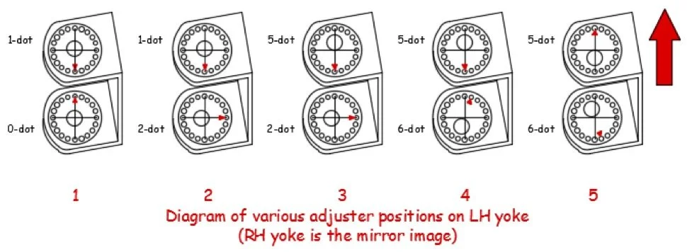
By mid-morning, you saw that you needed a bit less caster, so you changed the upper Pill to a 5-dot with the arrow pointing to the rear as shown above.
However, further testing led you to believe you wanted the absolute minimum caster you could get. So, referring to ‘4’ in the image above, you fitted a 6-dot Pill to the lower half of the yoke, but in order to get the camber to remain the same, you only required a 1-hole rotation (off the fore-aft direction) of this Pill. The arrow is still pointing to the right (to maintain negative camber) but the kingpin bolt hole is as far ‘back’ as possible to maintain as little caster as possible.
Much later in the day the rain set in heavily, and you decided you really needed maximum caster available but the camber should remain unchanged. To achieve this, you first altered the upper Pill by rotating it through half a turn, and then altered the bottom Pill by nearly half a turn as shown in ‘5’ in the image above. You effectively ‘flipped’ the lower kingpin hole about a horizontal line to increase the caster, but the arrow still remained 1-hole off the fore-aft direction, thus keeping the camber unchanged.
Hopefully this has given you a better understanding of to how to make logical adjustments to the front end without it being such a hit and miss affair as it might have been in the past.
Emile McGregor - MSA Technical Consultant